Zapytania o produkty 22 811 07 60
Bezpłatna wycena oferty@hts.com.pl
Zapytania o produkty 22 811 07 60
Bezpłatna wycena oferty@hts.com.pl
Kompleksowa oferta hvac
Kompleksowa i terminowa współpraca.
Popularne i cenione przez instalatorów urządzenia w atrakcyjnych cenach.

WENTYLACJA
Szeroki wybór elementów i materiałów wiodących producentów.
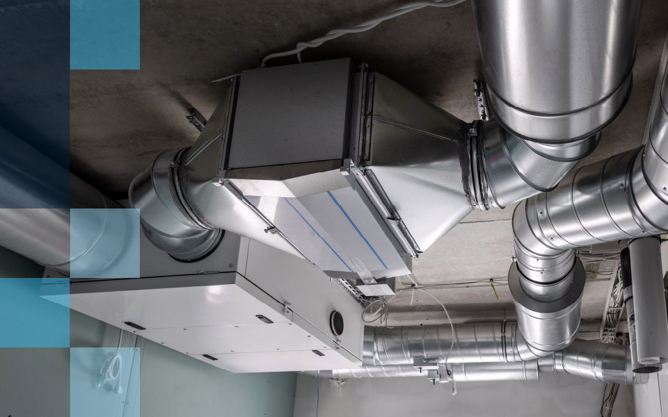
KLIMATYZACJA
Nowoczesne rozwiązania klimatyzatorów ściennych, kanałowych, podsufitowo- przypodłogowych,
kasetonowych i przenośnych.

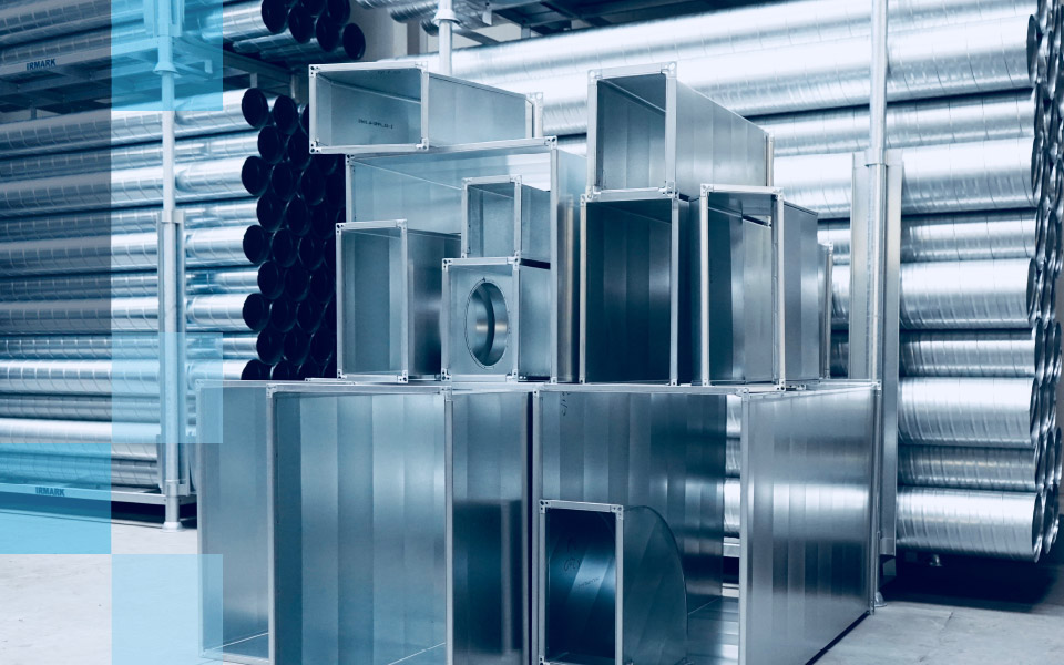
IRMARK
Korzyści
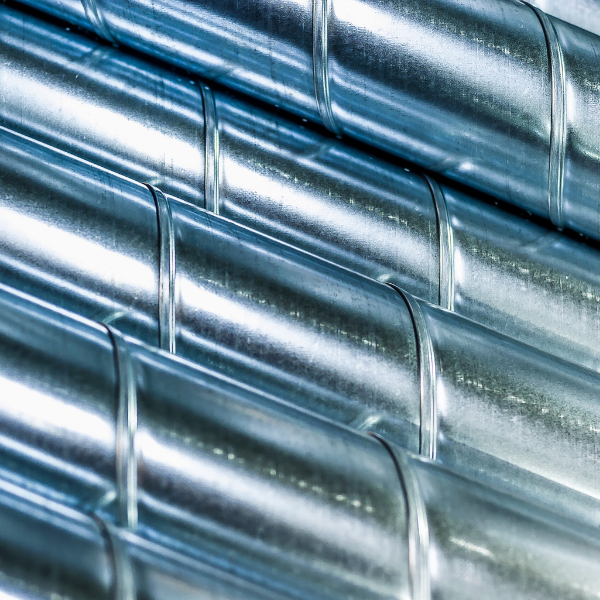
Rury spiralne i kształtki okrągłe w zakresie średnic 80 – 630mm dostępne od ręki. Realizujemy indywidualne i nietypowe zamówienia.
Korzyści

Jesteśmy bezpośrednim dystrybutorem popularnych i cenionych producentów branży HVAC, dlatego przygotujemy dla Ciebie dedykowaną i bezpłatną wycenę.
Producenci

Dostarczamy rozmaite elementy systemów klimatyzacyjnych oraz wentylacyjnych pochodzące zarówno od tych światowych producentów, jak i od mniejszych marek, które oferują artykuły doskonałej jakości.
Korzyści

Nieustannie poszerzamy współpracę z renomowanymi producentami HVAC. Dzięki temu oferujemy szeroki zakres produktów w atrakcyjnych cenach.
Newsletter

Chcesz otrzymywać informacje o nowościach, promocjach i wydarzeniach w HTS Polska? Zapisz się na naszą listę mailingową.
Korzyści
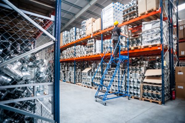
Posiadamy duże stany magazynowe w szerokim zakresie asortymentu, które pozwalają na odbiór lub dostawę towaru bezpośrednio z półki.

Masz pytania dotyczące oferty? Chcesz otrzymać bezpłatną wycenę?
Twoje zapytanie trafi do doradcy, który w ciągu 24 godzin oddzwoni lub odpowie mailowo na Twoje pytania.